A Practical Shadow Mapping Pipeline
Shadow mapping is a well known technique which was first introduced in 1978 by Lance Williams.
It has evolved to a lot of different variations and tweaks to be able to run at interactive frame rates, even though the foundation of the technique remains similar to the original:
- (1) Capture a depth buffer from the light point of view (called the shadow map). The projection used in this step is important as it will influence the type of light you want to represent; a directional light is represented as a cuboid since all casted rays from the light are parallel. We can use an ortographic projection for this type of light. For a point light, either one or several perspective projections can be used to represent all directions the point light is casting to.
- (2) For each fragment in the current point of view, transform it to light space coordinates and transform the light space coordinate to shadow map texture coordinates.
- (3) Compare the depth sampled at the coordinates in (2) to the depth saved in (1). If the depth sampled from the shadow map is greater than the light space depth of the current fragment, it means it is a shadowed pixel.
This post describes a practical approach to implementing shadow maps and is adapted to target mobile hardware using OpenGL ES 2.0 specifications. A modern Open GL implementation would look different from what is described here, as there are less hardware restrictions.
Implementing shadow maps for a multiplatform solution can be cumbersome. On mobile, a big share of the market may not support the extension that you need to implement it. Using a common solution between all the targets could be simpler than using extensions and discovering rendering issues on a few hardware targets later on.
Before starting to implement a rendering technique for a non-specific target, we can look at GPU hardware shares and extension support for each of the needed features:
In order to implement shadow mapping we need at least a framebuffer with a way to sample and store the depth from the light point of view. If we look at framebuffer with depth texture attachment, it is in this case an extension, as the target is Open GL ES 2.0. Now, looking at the extension OES_depth_texture description (from the khronos registry):
This extension defines a new texture format that stores depth values in the texture. Depth texture images are widely used for shadow casting but can also be used for other effects such as image based rendering, displacement mapping etc.
The great news is that, as of writing this post, it is supported by 94% of the hardware. One issue is that the attachment texture may or may not behave like you expect depending on the driver.
As per the OpenGL ES spec, there is no guarantee that the OpenGL ES implementation will use the type to determine how to store the depth texture internally. It may choose to downsample the 32-bit depth values to 16-bit or even 24-bit. There is currently no way for the application to know or find out how the depth texture (or any texture) will be stored internally by the OpenGL ES implementation.
The potential issues you can have with driver implementations and pitfall from not having the device with a specific GPU model supporting this extension to test on can be a risky choice.
The extension might not be implemented the way you think it is. A safer choice in this case it to use what is ensured to be supported on the official GL specifications of your target (in this particular case ES 2.0) and find the most commonly supported GL feature in order to have what is needed for the rendering technique.
Depth value storage
Depth write pass and generating the shadow map
In this implementation, the depth is stored as a packed RGB value in a color texture attachment of the framebuffer so that we don't rely on the depth texture attachment mentioned previously.
glGenTextures(1, &textureHandle);
glBindTexture(GL_TEXTURE_2D, textureHandle);

glTexParameteri(GL_TEXTURE_2D, GL_TEXTURE_MIN_FILTER, GL_NEAREST);
glTexParameteri(GL_TEXTURE_2D, GL_TEXTURE_MAG_FILTER, GL_NEAREST);
glTexParameteri(GL_TEXTURE_2D, GL_TEXTURE_WRAP_S, GL_CLAMP_TO_EDGE);
glTexParameteri(GL_TEXTURE_2D, GL_TEXTURE_WRAP_T, GL_CLAMP_TO_EDGE);

// Generate power of two texture size color attachment texture
glTexImage2D(GL_TEXTURE_2D, 0, GL_RGBA, 512, 512, 0, GL_RGBA, GL_UNSIGNED_BYTE, NULL);
glFramebufferTexture2D(GL_FRAMEBUFFER, GL_COLOR_ATTACHMENT0, GL_TEXTURE_2D, textureHandle, 0);
Non-Power-Of-Two textures can be an issue on mobile hardware (it may be available with the extension GL_OES_texture_npot), so instead of making a framebuffer with an attached texture of size of the default viewport resolution, the texture attachment is set to a 512x512 pixels texture resolution, which reduces the footprint of the shadow map at both depth sampling and depth writing but for the price of a lower quality result.
Since we use a RGB texture to store the depth result, we need a way to encode a float into an vec3. The fragment shader used to pack the depth value is the following:
// stores the 24 bits depth value in each 8 bits components, depth between 0..1
vec3 PackDepth888(float depth) {
    vec3 packedDepth;

    packedDepth.x = depth * 65536.0;
    packedDepth.y = depth * 256.0;
    packedDepth.z = depth;
    packedDepth.x = fract(packedDepth.x);
    packedDepth.y = fract(packedDepth.y) - packedDepth.x / 256.0;
    packedDepth.z = fract(packedDepth.z) - packedDepth.y / 256.0;

    return packedDepth;
}

void main() {
    // Store packed the depth in the framebuffer texture attachment
    gl_FragColor = vec4(PackDepth888(gl_FragCoord.z), 1.0);
}
A separate vertex buffer is used in this pass, with a vertex layout containing only the position of the meshes.
Using this technique, there can be precision issues, but we will make sure that the precision is maximized when generating the view frustum for this pass by optimizing the depth range.
Depth sampling pass
In this step, the values of the depth are unpacked and used to compare the depths in the fragment shader:
float UnpackDepth888(vec3 depthRGB) {
    return depthRGB.r / 65536.0 + depthRGB.g / 256.0 + depthRGB.b;
}

float Texture2DCompare(sampler2D depths, vec2 uv, float compare) {
    // Retrieve and unpack the shadow map depth coordinate
    float shadowMapDepth = UnpackDepth888(texture2D(shadowMap, uv).rgb);
    return step(compare, shadowMapDepth);
}

// Function returning 1.0 if the shadow coordiante shadowCoord is within the shadow, 0.0 otherwise
float GetShadow(sampler2D shadowMap, float shadowBias, vec4 shadowCoord) {
    // Transform homogeneous coordinates to texture coordinate [-1.0 .. 1.0] -> [0.0 .. 1.0]
    vec2 uv = shadowCoord.xy * 0.5 + vec2(0.5);

    // Transform depth to [0 .. 1.0] range, with a slight offset of shadowBias
    float shadowCoordDepth = (0.5 * shadowCoord.z + 0.5) - shadowBias;

    // Compare the depth value with the shadow map stored value at this shadow coordinate position
    return Texture2DCompare(shadowMap, uv, shadowCoordDepth);
}
shadowCoord is a value computed in the vertex shader and passed along the fragment shader as a varying:
shadowCoord = lightModelViewProjection * vec4(position, 1.0);
Where lightModelViewProjection is the transformation matrix transforming position to the light point of view.
When calculating the uv to sample the shadow map, a bias matrix can be used to reduce the number of operations in the fragment shader and offload it in the vertex shader. lightModelViewProjection would be multiplied by this bias matrix which is a matrix translating and scaling by $+0.5$ on every axis.
Shadow map bias
An issue with the texture resolution used for depths is shadow map acne. It can be solved by introducing a small bias when sampling the depth textures. Acne happens naturally because of the finite resolution of the texture used to store the shadow map. It manifests itself as a visual artifact.
Imagining the scene from the light point of view perceived through a grid, all grid bucket would be assigned a single depth, which can't represent the precise depth of all the geometry falling under that grid bucket from the camera point of view.
If the shadow map had an infinite resolution, all the texels would have an infinitely small area and the artifact would not be visible. So this issue is not due to the shadow map technique itself, it happens because of the representation that we have to use in order to implement it.
In practice, this issue can be solved by applying an offset to the shadow map to move the depth upwards in the direction of the current camera view, so that more points falls into it when comparing the depths. In this implementation, the preconditions of this bias are:
- When the light is parallel to the triangle, we want the bias to be maximized.
- When the light is perpendicular or behind the triangle, we want the bias to be minimized.
This technique is called slope scaled depth bias, because the bias is adaptive in function of the slope of the geometry.
A function that works for these preconditions is $tan(arccos(x))$ where $x$ is the visibility term $dot(\vec{N}, \vec{L})$ clamped between $0$ and $1$, where $\vec{N}$ is the surface normal, and $\vec{L}$ the normalized surface to light vector.
This function is also equals to $\frac{\sqrt{(1-x^2)}}{x}$ (demonstrated by using a few trigonometric formulas) which is usually less instructions in the shader. This bias can be applied either when rendering the shadow map or when sampling it.
Optimizing for depth buffer precision
To optimize the shadow map resolution and depth precision, the view frustum used to generate the shadow map should be as tight as possible. In my use case, the scene is composed of a few tiles where the scene bounding box can be updated every time a tile has moved.
The idea is to generate a matrix for the light camera that fits the bounding box of the scene, while being rotated by the light direction.
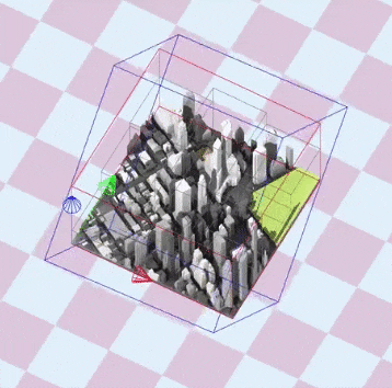
The documented code below generates an orthographic frustum perfectly fitting the bounding box of the scene:
// Assuming boundingBox encompasses the whole set of visible tiles for the current viewport:
FrustumFit Fit(BBox boundingBox, vec3 sunDirection) {
    FrustumFit frustumFit;

    // The initial local coordinate of the camera is a camera
    // pointing at (0.0, 0.0, 0.0), translated by -sunDirection
    vec3 up = vec3(0.0f, 0.0f, 1.0f);
    vec3 center = vec3(0.0f);
    vec3 at = -sunDirection;
    frustumFit.view  = lookAt(at, center, up);

    // Kill translation component (last column of the view
    // matrix) since we only want the rotation components
    frustumFit.view[3][0] = 0.0f;
    frustumFit.view[3][1] = 0.0f;
    frustumFit.view[3][2] = 0.0f;

    // Initialize the box 8 corners of the scene
    vec3 BBoxCorners[8] {
        vec3(boundingBox.max.x, boundingBox.min.y, boundingBox.min.z),
        vec3(boundingBox.max.x, boundingBox.min.y, boundingBox.max.z),
        vec3(boundingBox.max.x, boundingBox.max.y, boundingBox.min.z),
        vec3(boundingBox.max.x, boundingBox.max.y, boundingBox.max.z),
        vec3(boundingBox.min.x, boundingBox.min.y, boundingBox.min.z),
        vec3(boundingBox.min.x, boundingBox.min.y, boundingBox.max.z),
        vec3(boundingBox.min.x, boundingBox.max.y, boundingBox.min.z),
        vec3(boundingBox.min.x, boundingBox.max.y, boundingBox.max.z),
    };

    // Transform each of the box corner to light view space
    BBox lightViewSpaceBBox;
    for (int i = 0; i < 8; ++i) {
        vec3 lightViewSpaceBBoxPoint = frustumFit.view * vec4(BBoxCorners[i], 1.0f);

        // Merge the light view space bbox with this newly transformed point
        lightViewSpaceBBox = merge(lightViewSpaceBBox, lightViewSpaceBBoxPoint);
    }

    // Camera looking at -z, apply its min and max to make its frustum tightly fitting
    double far  = std::max(-lightViewSpaceBBox.min.z, -lightViewSpaceBBox.max.z);
    double near = std::min(-lightViewSpaceBBox.min.z, -lightViewSpaceBBox.max.z);

    frustumFit.projection = ortho(
        lightViewSpaceBBox.min.x, // left
        lightViewSpaceBBox.max.x, // right
        lightViewSpaceBBox.min.y, // top
        lightViewSpaceBBox.max.y, // bottom
        near, far);

    return frustumFit;
}